skip to Main Content
Flexible Production With Bending Robots And Encoding Automation

Flexible Production With Bending Robots And Encoding Automation

The Automation trend towards flexibility in machining processes with a high degree of automation is enduring in many sectors. Contributed by transfluid

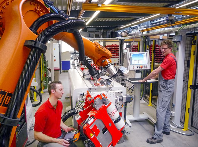
An efficient bending system for short and long pipes has been developed by trans fluid, and the automation system bends 6 m long pipes with small diameters at a consistently high speed. The production unit is capable of producing shorter pipelines of 500 mm featuring diverse bending geometry in large quantities. Handling coated pipes during processing can be demanding because of sensitive surfaces thus, special care and treatment are required during processing.

Chain Conveyor And Clever Encoding

To ensure that production Automation can be implemented safely, quickly and thoroughly, a machine shop equipped has equipped itself with two robots that are used as bending machines with different magazines. One magazine is a “chain conveyor”. It guides long pipes to the bending robot.

According to the markings placed on the pipes by the encoding beforehand, the robots are able to detect which geometries need to be produced. In this case, they are capable of bending a long pipe from one side to the centre.

Following processing, the workpiece is placed on a slide. The bending cell also possesses a separate step conveyor. This feeds in short pipe lengths, including two different pipes if this is required. Depending on the case at hand, each robot processes a different geometry or pipes with another diameter. This enables a large series of short components to be processed efficiently at the same time. Long components can be processed just as effectively.

Flexible Production With Bending Robots And Encoding Automation

Achieving Versatility

“An additional challenge for the development of our solution was that all the pipes have previously end formed ends on both sides or they already have cutting rings mounted,” said Stefanie Flaeper, general manager at trans fluid.

“With robot technology, bending geometry may be started at an extremely short distance from the bend on both previously mounted ends. And the process—for example preparing the ends first and then bending—is able to be implemented consistently for any pipe with this bending technique,” explained Ms Flaeper.

This allows prior processing of the ends to be significantly cheaper and faster, and with this process, there are no geometric limitations and the pipe can be sealed beforehand with caps. This makes it immediately available for use after bending.

Bending Directly From CAD Automation System

In addition to flexibility, an additional strength of the automation system offers another advantage that cannot be underestimated: The robots do not need to be programmed. As with any conventional bending machine, the necessary data may be loaded into the bending robots with a data file directly from the CAD system and transformed into a bending geometry. This makes the psychological barrier raised by programming a thing of the past, and the systems can be linked online with all relevant measurement systems.

CHECK OUT THESE OTHER ARTICLES

Nissan Teaches Robots To Make Replacement Parts For Cars
Universal Robots Future-Proofs Production Processes In Southeast Asia With Collaborative Robots
Universal Robots Launches Heavy-Duty Payload Cobot For Collaborative Automation
Walter’s HU5 Geometry Enhances Capabilities Of Cutting Machines
Hypertherm Implements Strategies to Enhance Preventive Maintenance Program In Asia
ANCA Motion’s Multi-Axis Servo System Conserves 96 Percent Of Energy Wastage
Bystronic To Complete Modernisation Of Production Facility
Tungaloy Expands HP Geometry Line of T-CBN Inserts
OnRobot Wins Gold in LEAP Awards
Industrial Robots: Robot Investment Reaches Record US$16.5 Billion

WANT MORE INSIDER NEWS? SUBSCRIBE TO OUR DIGITAL MAGAZINE NOW!

FOLLOW US ON: LinkedIn, Facebook, Twitter


Datakit CAD Data Exchange Software Conversion Tools

Datakit CAD Data Exchange Software conversion tools

Datakit’s new version of CrossManager, CrossCad/Plg and CrossCad/Ware adds several improvements to Datakit’s interfaces. These applications can now read new versions of CAD formats: SOLIDWORKS 2018, NX 12 and DWG 2018.

CrossManager is now able to convert 3D models to .prc files. This format allows encapsulating 3D data in a PDF. Thus, the software enables the integration of models coming from most of 3D formats in a PDF. Conversion to PRC is available from more than 20 CAD formats.

– The Revit format (.rvt files) reading is now available, expanding Datakit’s BIM data conversion offering, begun last year with the IFC format.
This new reader enables software vendors to add Revit import capabilities to their own application by using CrossCad/Ware. It also enables end-users to convert Revit files to IGES, STEP, 3DPDF and PRC with CrossManager.
This new interface is able to read geometrical data along with colors and instances contained in Revit 2017.x files


CHECK OUT THESE OTHER ARTICLES

Big Presence For Taiwan At EMO 2019
Mastercam: CAD/CAM Software
Idemitsu Establishes Lube Sales Company In The Philippines
MVTec HALCON 19.11: Standard Machine Vision Software With New Functions
Etihad Engineering Sets Up 3D printing Lab in Abu Dhabi, Receives Region’s First Approval to 3D Print Aircraft Parts
Creaform Moves Offices In Singapore
EMO 2019: ANCA To Launch Latest Generation Of ToolRoom Software
Siemens: Solid Edge ST9 Software For CAD
Interview With UTAC: Shaping 2019
Hexagon Touch Probe Transforms Thickness Measurement on Machine Tools


WANT MORE INSIDER NEWS? SUBSCRIBE TO OUR DIGITAL MAGAZINE NOW!

FOLLOW US ON: LinkedIn, Facebook, Twitter


The Way To Efficiency & Functionality

The Way To Efficiency & Functionality

The measurement service provider Lometec upgraded the measuring software for its tactile Wenzel coordinate measuring machines from Metrosoft CM to Metrosoft Quartis. Lomotech’s Chief Executive Officer Jörg Werkmeister and Technical Director Marc Lange talk about their practical experience using the example of a dimensional inspection of a turbine blade testing device.

Read More
Addressing MEMS Challenges (Part I)

Addressing MEMS Challenges (Part I)

Overcoming design challenges for mircoeclectromechanical systems (MEMS) in an IC-focused environment. By Nicolas Williams, product marketing manager and Qi Jing, technical marketing engineer, Mentor Graphics

Microelectro-mechanical systems (MEMS) have been growing rapidly ever since it became possible to fabricate MEMS devices using modified semiconductor device fabrication technologies. Layout tools that are widely used in IC design naturally become the tool of choice for MEMS layout design.

Although IC layout tools are quite mature and feature-rich for IC applications, many of them lack the capabilities to efficiently handle the challenges MEMS layout imposes. That is why unique MEMS-oriented features are needed in IC tools to address the specific requirements of MEMS layout design and to make the design process fast, easy and accurate.

A big difference between MEMS layout and IC layout is the use of unique, irregular shapes. Unlike conventional CMOS IC design, where layout shapes are usually Manhattan style (such as rectangles and rectilinear polygons) or polygons with 45-degree edges for routing, MEMS design utilises a much broader variety of geometries, due to its wide applications in the mechanical, optical, magnetic, fluidic and biological fields.

The support and ease of use for implementation of irregular shapes, including curves and all-angle polygons, becomes a critical criterion differentiating MEMS-oriented CAD tools from conventional IC-oriented tools. Most layout and verification tools are focused and optimised on IC designs and are not suitable for irregular shapes needed for MEMS designs. MEMS designers need layout and verification tools that can handle challenges that curved or all-angle objects presents. Also, designers need tips and tricks on how to handle false errors that result from rules that are optimised for orthogonal geometry.

Overcoming Limitations Of Mechanical CAD Tool

Unlike traditional mechanical CAD tools, where “zero-width” lines are common, MEMS layout requires all geometry to be represented as “closed” or “filled” polygons. This is needed to define the light and dark regions of the mask. One limitation with some mechanical CAD tools is that they cannot represent a filled polygon easily and any drawing done in these tools usually results in the polygon being represented as several “zero-width” line segments.

When importing DXF files (a common format used to transfer geometry from mechanical CAD tools), MEMS can search for segments having endpoints within the user-specified tolerance and try to reconstruct closed polygons as seen in Figure 1.

Overcoming Limitations Of Mechanical CAD Tool

If a closed polygon is found, the individual segments will be replaced by a single polygon. The endpoints of the line segments do not have to match exactly. MEMS allows the user to specify the largest gap between segment endpoints when joining them into a polygon. When sending the MEMS design to the foundry for fabrication, the user typically will export the design in GDSII format. Since the GDSII format does not support curves, a conversion is needed for circles, pie wedges, curved-sided polygons and tori to all-angle polygons that approximate the curve when GDSII mask data is exported.

MEMS automatically performs this conversion, and additionally issues warnings if the design contains a wire or polygon with more than 200 vertices, since GDSII has a limit of 8,192 vertices, and 200 vertices is a traditional best practice limit. The user can then specify a maximum number of vertices that each polygon should have and if it exceeds this maximum, the polygon will be automatically fractured into smaller polygons with fewer vertices by Tanner L-Edit MEMS.

All-angle polygons can also be converted back to curved polygons. Sometimes, a GDSII file, where curves are not preserved, needs to be read back in for design revision; or curves need to be recovered from the result of an advanced editing operation such as Boolean operations, making it easier to edit.

To achieve good curve recovery, MEMS searches all-angle polygons for arcs with eight or more vertices and replaces the multiple adjacent segments with curved edges, provided that those vertices lie on an arc with no more than one manufacturing unit radius error (Figure 2). Such conversion capabilities make it much more convenient and accurate for users to re-edit curved objects.

Overcoming Limitations Of Mechanical CAD Tool

Curve Conversion To All-Angle Edges

Curved polygons need to be converted to allangle polygons when doing some advanced editing operations, when running design rule checking (DRC) and when exporting to GDSII. The all-angle approximation must represent the actual curve as accurately as possible.

In some CAD tools, curves are converted based on a specific number of vertices, which does not guarantee the precision between curves of different sizes. MEMS converts curves based on the manufacturing grid, which adjusts the number of vertices to use during conversion based on the size of the curves to have maximum precision.

To show the difference between the approach of Tanner L-Edit MEMS and other CAD tools, three circles with a 5-μm, 50-μm, and 250- μm radius were converted in Figure 3 to all angle polygons using a fixed number of vertices which is common in other CAD tools.

Curve Conversion To All-Angle Edges

They were also converted using the MEMS approach. Notice that for small curves such as the 5-um radius circle, both approaches do a good job approximating the curve compared to the original curve and have about the same error.

For larger curves, however, the error rate increases for the fixed number of vertices method to be as much as 0.3 μm for the 250 μm circle. Since MEMS uses the manufacturing grid to calculate the number of vertices, the error is on average, less than the manufacturing grid of 0.01 μm.

Even though edges are smoothed when fabricated, this error can affect how the resulting MEMS structure performs if the error is too high. Also, this conversion error can cause problems when doing Boolean operations on curved geometry and can cause many false DRC errors.

To be continued… Addressing MES Challenges (Part II)

APMEN Metrology

Machining Centres: Measurement Made Easy

Machining Centres: Measurement Made Easy

Model and mould-maker Sammer, Machining Centres located in Eugendorf near Salzburg, Austria, is mostly engaged in the production of moulds for the automotive industry, including cylinder heads, crankcases and transmission housings. By Winfried Weiland, head of marketing, Blum-Novotest GmbH.

Read More
Combining Gear & 3D Coordinate Metrology For More Flexibility

Combining Gear & 3D Coordinate Metrology For More Flexibility

Complex components can be analysed in a fully function-orientated manner with a combination of gear and 3D coordinate metrology. By Heinrich Brüderle, sales manager Europe and America, Wenzel

The requirements for metrology regarding throughput and flexibility are steadily increasing. Not only are individual measuring methods becoming faster—measuring systems should also become universally deployable. Ideally, different kinds of measurement tasks should therefore be able to be performed by one single system and in one process.

Entire Metrological Analysis

In conjunction with a change rack, it is possible to automatically switch between different probe configurations during the course of a measurement program. An intervention by the operator is not required and thus reproducible, user-independent measurement results can be achieved.The combination of gear and 3D coordinate metrology not only allows the complete measurement of various gear, prismatic and free-form components but also the entire metrological analysis with regard to form and location. This means that complex components can be analysed in a fully function-orientated manner. This is particularly evident in the case of components where gearing and geometrical elements are combined, such as planetary gear carrier sets.

Gear and 3D measuring systems normally differ in their construction. Gear measuring systems are conceived for measuring rotationally symmetrical workpieces with three linear and one rotary axis. Gear measurements can be performed according to gearing principles with the aid of the integrated rotary table, thus enabling optimum tactile contact conditions.

On the other hand, 3D coordinate measuring systems are more universally applicable due to their rectangular measuring volume, with prismatic and free-form components being typical.

Optimal Utilisation

The accuracy and acceptance procedures are also based on the respective application fields. Gear measuring machines are accepted according to the VDI/VDE-Directives 2612/13 and 3D measuring machines according to the ISO 10360 series of standards. The data from the 3D coordinate systems describe the precision of single-point probing and linear measurements. These are performed on reference standards such as spherical reference standards, step gauges or ball bars.

In order to combine both metrology principles, both acceptance procedures are used on a combination machine. In favour of achieving an optimal precision, the smallest residual, structural errors are captured and compensated by CAA laser compensation. These errors are reduced to a minimum in various ways, such as structures made with mechanical precision and the application of hand-lapped granite guideways.

Measuring Against CAD Data

If a 3D coordinate measuring machine is equipped with an integrated rotary table, the basics of gear metrology can be combined with the flexibility of 3D coordinate measuring machines. This procedure provides the possibility to use gear measuring software as well as 3D measuring software on one measuring machine.

In this way, prismatic components, for example cases can be programmed and measured against the CAD data, with extensive shape and position analysis also being feasible. In particular, position tolerances can be evaluated this way both in terms of production as well as function. On request, certain machine sizes can be equipped with tailstocks for the measurement of shafts.

The optimal utilisation of the coordinate measuring machine is due to the application of the 3D and gear measuring software. A broad range of gear measuring machines offers solutions analysis of minute gears up to large ring gears and bearings with a diameter of up to 6,000 mm.

APMEN Metrology

CHECK OUT THESE OTHER ARTICLES

Blum-Novotest To Highlight Measuring, Testing Technology at EMO 2019
Perfect Combination – New Hybrid Laser Measuring System
Aicon: Automated Scanning In Production
Unlock The Hidden Potential Of Your CMMs
The E-Mobility Roadmap: Speeding Up Tool Development With A High-Accuracy CMM
Overcoming Challenges In Production With Multisensor Measuring Machines
Rock Solid Foundations: Granite For High Accuracy Measurement
ZEISS Completes GOM Acquisition

WANT MORE INSIDER NEWS? SUBSCRIBE TO OUR DIGITAL MAGAZINE NOW!

FOLLOW US ON: LinkedIn, Facebook, Twitter


Siemens: Solid Edge ST9 Software For CAD

Siemens: Solid Edge ST9 Software For CAD

Siemens has launched the new Solid Edge ST9 software for mainstream CAD. It allows easy access to the full capabilities of Solid Edge with cloud-based licensing, user preferences, and collaboration tools.

The built-in data management capabilities with zero IT support requirements enable users to easily index CAD models and allow users to take control of large volumes of CAD data, while the migration tools enable fast conversion of legacy design data from any CAD system. Additionally, a Solid Edge 2D to AutoCAD software export tool ensures an easy mapping of Solid Edge drafting elements to AutoCAD.

New cloud capabilities provide more flexible deployment options, improved user access and collaboration across remote designs teams. Licenses and user preferences can be stored on the cloud enabling users to easily access their personal environment at any time.

Solid Edge ST9 also adds data storage options via cloud-enabled vaulting so users can store and share design data in a controlled manner with external suppliers and customers, using popular software like Dropbox, OneDrive software, Google Drive online storage service and Box.

APMEN Products

CHECK OUT THESE OTHER ARTICLES

GEORG At EMO 2019: Digital Twin Becomes Real
ZYFRA Showcases AI Predictive Maintenance Software At EMO 2019
HAIMER To Showcase Latest Technologies And Solutions At EMO 2019
Walter’s HU5 Geometry Enhances Capabilities Of Cutting Machines
Taking metal to the cloud
The Carefree Package For The Entry Into Bending
MVTec HALCON 19.11: Standard Machine Vision Software With New Functions
Hexagon Launches QUINDOS 2019.2
Round Tool Concepts: Indexable, Solid or Both
Hypertherm Releases Major Version Update Of Robotmaster Robot Programming Software

WANT MORE INSIDER NEWS? SUBSCRIBE TO OUR DIGITAL MAGAZINE NOW!

FOLLOW US ON: LinkedIn, Facebook, Twitter


LVD: Cadman-SDI Smart Drawing Importer Module

LVD: Cadman-SDI Smart Drawing Importer Module

LVD’s new Cadman-SDI module simplifies 2D and 3D CAD file import and calculation of cost drivers so users can quickly and accurately create job estimates.

A CAD drawing file is imported into the module via simple “drag and drop”. Once imported, the file is converted to OSM (Open Sheet Metal) format and stored in the central Cadman database.

Stored OSM files are immediately accessible for all other modules of the Cadman suite for efficient generation of laser, punching, bending programmes and jobs scheduling. All data is visible at a glance on the control screen.

It features the integrated BrisCAD, a robust 3D direct modelling CAD package. BrisCAD allows the 3D drawing to be reviewed in detail, modified or corrected as required.

APMEN Products


CHECK OUT THESE OTHER ARTICLES

SCHUNK Releases Versatile Clamping Module For Automated Machine Loading
Siemens: Solid Edge ST9 Software For CAD
OMAX Presents Waterjet Cutting Technology at EMO 2019
Hypertherm Releases Major Version Update Of Robotmaster Robot Programming Software
Hypertherm ProNest 2019
TRUMPF Is Expanding The Scope Of 3D Printing
ZEISS Completes GOM Acquisition
EMO 2019: ANCA To Launch Latest Generation Of ToolRoom Software
Faro Launches Cobalt Design Structured Light 3D Scanner
GEFERTEC At EMO: New-Generation Machines And Applications For 3D Metal Printing

WANT MORE INSIDER NEWS? SUBSCRIBE TO OUR DIGITAL MAGAZINE NOW!

FOLLOW US ON: LinkedIn, Facebook, Twitter


Back To Top