API presents the new and improved vProbe in online demos. vProbe achieves CMM-level accuracy when measuring components of any volume. API’s new vProbe is smaller and lighter. It features automatic probe recognition, smart buttons, and has a working battery life of up to eight hours.
“The new and improved API vProbe tactile measuring sensor provides the ability to perform accurate CMMstyle measurements directly on the production floor. Integrated with the API Radian Laser Tracker series, vProbe significantly enhances the measuring capabilities and functionalities of traditional Laser Trackers.”, summarises Jan-Hendrick Lott, General Manager von API für die Region EMEA, on the performance of the new measuring sensor.
Accurate 3D measurements of internal and external features
vProbe is a wireless, hand-held, lightweight, tactile probe with easy hold grip that allows users to perform extended coordinate measuring functions by inspecting intricate internal and external features or part characteristics providing fast and accurate dimensional measurements.
Easy, error-free application through Smart Buttons for common software functions
vProbe offers more versatility than a portable arm CMM, greater accuracy, and consistent measurements making it inherently more suitable for medium and large parts. The RFID probe stylus recognition feature of the New vProbe eliminates the need to manually select the probe stylus, ultimately removing potential for error. Additionally, Smart Buttons create a better user experience, minimising trips to the computer to select common functions which are now integrated in the probe. Dynamic tactile scanning capability provides instant coordinate feedback, and the integrated battery provides up to 8 hours of measurement activity. Styli lengths up to 500mm with a variety of tip sizes can be accommodated.
Applications of the 3D measuring system – demo options both on site and virtual
vProbe is ideal for applications in component measurement, hidden point measurement, quality assurance, fixtures, jig and tooling, reverse engineering, scanning and all other precision measurement applications.
When it comes to metrology, here’s how customers can boost confidence, accelerate delivery timelines, and reduce scrap and rework rates all at once. Article by Jim Cassady and Jutta Mayer, FARO Technologies.
In the world of manufacturing, dimensional control is fundamental to successful part assembly. It determines part-to-part variation, establishes part-to-CAD comparison to check whether specs are met, and ensures proper final fit. Beyond getting part geometries right, however, there are additional reasons for maintaining standards in accordance with design specifications.
Investing in precision equipment for measuring and aligning components helps ensure that everything fits the first time around without any unnecessary rework, saving time, and other resources for a company. Further, more serious consequences such as equipment failure or production delays can be avoided when alignment, measurements, and inspections are conducted properly and at appropriate phases of production.
A ‘Greater’ Need for Precision
For industries such as aerospace, automotive, shipbuilding, heavy equipment manufacturing, and many others that handle large components and assemblies, measurement and alignment tasks are a considerable challenge in the overall production process. On the surface, these challenges may not seem too different from what most manufacturers typically encounter. Yet, the difficulties, as well as the consequences of missed specifications, are magnified owing to the size of the objects being built.
Manufacturers that handle large workpieces would candidly share that as product size increases and part geometry grows more complex, it becomes harder for them to perform measurements and inspections accurately. Conventional hand tools such as rules, gauges, calipers, micrometers, squares, and protractors are effective up to a point, but they are also demanding in terms of time and operator skill, often making them prone to human error.
The use of large, fixed coordinate measurement machines (CMMs) in quality labs is impractical as many workpieces cannot be moved to the lab for measurement and inspection. For example, if a ship is dry-docked for a limited time for retrofitting purposes, transporting parts that would fit on a CMM into a quality lab would not be practical. In addition, fixed CMMs are limited in terms of the size of the parts they can inspect and become costly in large working volumes.
Portable 3D Technology to the Rescue
Portable 3D coordinate measurement devices have long become the choice solution among manufacturers for large-volume measurement, as they combine accuracy with flexibility. Compared to conventional hand tools, portable 3D technology offers manufacturers a much higher level of precision, efficiency, and productivity all at once. Unlike fixed CMMs, these solutions require much less capital investment at the onset and are robust enough to perform even in a non-controlled environment, such as on the production floor, in a dry-dock or hangar.
The resulting ability to deploy measurement devices right where the manufacturing process takes place accelerates execution timelines and allows manufacturers to deliver quality products with greater confidence. What this means for large-part manufacturers is that, instead of settling for hand tools or a bulky fixed CMM set-up, they can opt for alternatives that offer the right mix of performance, cost, and flexibility.
The introduction of precision and high-performance moulds has led to ever-increasing demands on mould manufacturers in recent years. Since the precision of the shape is determined by the dimensional accuracy of the electrode, it is essential to carry out accurate measurements of the size and shape of the electrode before processing the shape. Article by WENZEL.
The LHF 2517 is a large portal measuring instrument of gantry and bridge construction for medium and large workpieces. (Courtesy of WENZEL)
Changyuan Technology (Tianjin) Co. Ltd (CHYUAN) specialises in the development and manufacture of automotive injection moulds. With a planned production capacity of 450 million moulds, the company aims to develop into one of the largest single manufacturers of automotive injection moulds in northern China.
For increased efficient production of precision moulds, CHYUAN has commissioned an automated production line for electrodes and mould inserts, which enables the integration of electrode disassembly, processing, inspection, repair and offline processes. Since the measuring system used is the key to quality assurance, CHYUAN prefers the use of coordinate measuring machines (CMMs).
A CMM provides one of the most effective solutions for measuring and collecting dimension data. First, it can replace a variety of surface-to-surface measurement tools and expensive combined gauges. Secondly, the CMM can reduce the time required for complex measurements from hours to minutes. Thirdly, it guarantees both the efficiency and accuracy of measurement of size, shape and positional tolerance of the electrode.
Automated Measurements in the Direct Production Environment
CHYUAN relies on the WENZEL coordinate measuring devices XOrbit77 and LHF 2517. The figures represent the measuring volume in the X and Z axes of 700 mm x 700 mm and 2500 mm x 1700 mm, respectively. The XOrbit was seamlessly integrated into the production line for electrodes and mould inserts for automated 3D coordinate measurement in 2019. The CNC measuring device is ideally suited for the shopfloor environment and can be equipped with switching measuring and optical sensors. The XOrbit offers excellent value for money with high mechanical precision and low operating costs.
Meanwhile, the LHF 2517 is a large measuring instrument in gantry and bridge construction for medium and large workpieces. The floor-level design of the LHF allows easy assembly with large parts with high freedom of movement for the user. The double drive in the Y-axis of the LHF ensures high measuring speeds and excellent stability of the guides.
The demand for measurement tasks in which tactile and optical sensors are jointly used is set to rise more and more in the future. Here’s a technology that saves time and operating costs without compromising on reliable, precise measurement results. Article by ZEISS.
When it comes to maximum precision, coordinate measuring machines (CMMs) are an indispensable tool in industrial applications. To date, they have mainly been used for tactile measurement. In recent years, the need for and use of optical sensors is becoming increasingly significant. There are many reasons for this: the technical advancements being experienced in many sectors require increasingly complex parts; digitalisation and Industry 4.0 are changing manufacturing processes and thus also quality assurance; and customers have higher quality and efficiency demands, in general, nowadays. Many companies are therefore expressing the need for an all-round solution, that is, tactile and optical measurement on a CMM.
One example is the ZEISS CONTURA. Already in its fifth generation, ZEISS CONTURA is equipped with mass technology (multi-application sensor system) as standard, enabling tactile and optical measurement on a single machine. The multisensor platform means it is compatible with a variety of sensors from the ZEISS portfolio: sensors on the continuous articulating unit, star styluses or long styluses, optical or tactile, and scanning or with single point measurement. Thanks to the mass technology from ZEISS, the user acquires maximum flexibility.
Simple Sensor Switch
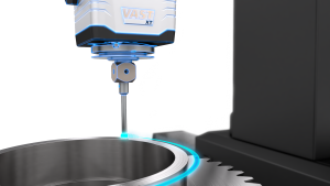
With ZEISS mass technology, when the sensors are operated on the continuous articulating unit, they are switched automatically. This applies to all optical sensors as well as the ZEISS VAST XXT and XDT tactile sensors.
During the sensor switch, the continuous articulating unit aligns itself in a 90 deg position, with the sensor pointing downwards. It then moves to a free place in the sensor magazine, which is usually attached to the reverse end of the measuring stage, pushes the safety flap back, moves downwards into a groove, and releases the magnetic locking mechanism in order to unlock the sensor. The new sensor is picked up in a similar way: the continuous articulating unit moves backwards and opens the safety flap, moves downwards and picks up the sensor magnetically. On the plate holding the sensor, there are three cylinder-shaped rollers which ensure that the counterpart is precisely positioned on the sensor.
Therefore, even after frequent switches, the sensor is reproducibly situated at the correct point. The measurement uncertainty is not increased by any significant extent due to the sensor bracket. Users do not need to worry that the accuracy may get out of hand if the sensor is switched repeatedly. Due to the high repetition accuracy during the sensor switch, it is not necessary to recalibrate the sensor after the switch has been carried out. Since the automatic exchange itself takes only a few seconds, ZEISS mass technology means an enormous boost in productivity – and thus time and cost savings.
The continuous articulating unit itself, as well as tactile probes from the ZEISS VAST XT gold series, are attached to the ZEISS CONTURA by means of a dovetail mechanism. This is a groove which the counterpart on the sensor or on the continuous articulating unit is pushed into and which, due to its shape and precise processing, does not allow any leeway whatsoever. Handling is easy too: the measuring technician loosens a screw mechanism and pulls the sensor or the continuous articulating unit out of the groove and inserts the new sensor. The sensor switch is completed within seconds. However, a repeated calibration is crucial during a sensor switch and is especially useful when using an active tactile sensor such as ZEISS VAST XT gold, which offers high measuring accuracy, short measurement times and long stylus lengths. All other sensors—passive, tactile as well as optical—are ideally operated on the continuous articulating unit—with all the advantages of the automatic sensor switch of ZEISS mass technology.
Optical Measuring Procedures
Optical measuring procedures are particularly interesting in parts with complex shapes if the user is required to record the surface quickly. This is useful in production in order to safeguard the quality of process steps, such as casting metal blanks or after grinding, in order to obtain a quick comparison between the current and target values of the CAD file. Optical sensors are also ideal for reverse engineering, that is, in order to generate CAD data from a prototype. Optical measurement procedures are often faster than tactile procedures and nonetheless sufficiently accurate. For sensitive parts which may not be touched, there is no alternative to optical sensors.
Various optical sensors can be more suitable depending on the application:
Chromatic-confocal white light sensor: This type of sensor is used in the area of application of workpieces with sensitive, soft, reflective or low-contrast surfaces. It records the surface of sensitive parts which may not be touched—where tactile styluses are obviously excluded. This sensor even detects transparent painted surfaces above underlying metallic layers and is suitable for transparent layers with various refractive indices. For this purpose, the sensor uses white light, which includes all wavelengths of the visible spectrum. Even strongly reflective surfaces such as glossy metal parts either in automotive and engineering or knee implants do not need to be sprayed with a contrast medium, which other optical measurement methods usually require.
ZEISS offers such a pioneering chromatic confocal white light sensor: DotScan. The sensor can be rotated and swiveled in 2.5 deg steps so that it is always optimally aligned towards the surface. In conjunction with the optional rotary stage, it is suited, for example, to the quality control of parts with complex shapes as well as glass surfaces.
Triangulation laser: suitable for the fast recording and inspection of freeform surfaces such as those required by casting tools or castings, bent sheets or plastic covers also require non-tactile measurement. The sensor moves above the part at a distance of a few centimetres and projects a line with laser light, which is thrown back from the surface into a sensor chip. Based on the angle, the sensor determines the distance from the part and therefore its surface shape. Each time the light is projected, the sensor determines hundreds of points in a line.
The maximum possible number of points with ZEISS LineScan is 700,000 measurement points per second—the number of rough points which are then calculated to provide actual measurement points in the software. Thus, point clouds which fully record the complex surfaces of even larger parts can be created in just a few minutes. Based on the point cloud, the ZEISS CALYPSO software calculates a chromatic representation using the CAD target data record as a comparison.
2D camera sensor: for very small or two-dimensional parts such as circuit boards or flat parts made of sheet metal that cannot be measured using contact means because it may result in deformation of their surfaces, the ZEISS ViScan 2D rotatable camera sensor is the ideal solution. It is capable of recording height-related information, thanks to the Autofocus function, as well as features various objective lenses, enabling increased flexibility in the working distance, area being recorded and accuracy.
Creaform has released its latest version of the MetraSCAN 3D lineup, the company’s advanced optical CMM scanner designed specifically to perform metrology-grade 3D measurements and inspections. As the fastest and most accurate portable optical CMM scanner, the MetraSCAN BLACK can be seamlessly integrated in any quality control, quality assurance, inspection, MRO, or reverse engineering workflow and operated by users of any skill level in any type of environment.
The MetraSCAN BLACK dimensional metrology system has been developed to measure complex parts and assemblies from an array of industries and manufacturing processes, such as automobile, aeronautics, power generation, heavy industry, metal casting, metal forging, sheet metal, plastic injection, composites, etc.
Featuring unmatched performance and speed for optimized 3D measurements
4X faster: Featuring 15 blue laser crosses for larger scanning area that take up to 1,800,000 measurements per second and live meshing, ultimately cutting down the time between acquisition and workable files.
4X resolution: MetraSCAN BLACK features a measurement resolution of 0.025 mm (0.0009 in) to generate highly detailed scans of any object.
More accurate and traceable measurements: High accuracy of 0.025mm, based on VDI/VDE 2634 part 3 standard and tested in a ISO 17025 accredited laboratory, ensures complete reliability and full traceability to international standards.
Shop floor accuracy: The MetraSCAN BLACK features a unique and patented dynamic referencing that compensates for surroundings instabilities.
Maximum versatility: Masters complex, shiny and highly detailed parts
No warm-up time: Operators can be up-and-running in minutes.
Touch probing capability: When paired with the HandyPROBE, the MetraSCAN BLACK lets users harness the power of both 3D scanning and probing for a complete, streamlined inspection process.
Available in BLACK and BLACK|Elite: Customers can choose from two models based on their needs: speed, part complexity, accuracy, etc.
“Today’s manufacturers are facing tremendous challenges. They are under increased pressure to accelerate their time to market in order to remain competitive on the global scale. Product quality issues impact scrap rate, production ramp-up, production rate, and downtime, ultimately affecting production costs and overall profitability. Manufacturers need to rely on innovative 3D measurement technologies, like the MetraSCAN 3D, in order to refine their product development and quality control processes,” explained Guillaume Bull, Product Manager at Creaform.
“This new version of the MetraSCAN 3D takes dimensional measurement speed, accuracy and versatility to a whole new level. We believe manufacturers will appreciate its performance within their workflows.”
FARO Technologies, Inc. has released its most affordable and accurate 3D portable coordinate measurement machine (CMM): The FARO Gage. Ideal for small and medium-sized businesses performing high-accuracy tasks, the Gage is the most intuitive, ergonomic, and versatile articulated portable FaroArm, enabling machine shops to perform their most demanding 3D inspections in record time.
The all-in-one-solution also reduces calibration costs and minimizes clutter, replacing traditional hand tools such as calipers, micrometers, and height gauges, while providing 20 percent more reach than the previous-generation Gage arm. Lightweight and portable but with the precision of a lab instrument and the ruggedness of a shop floor device, the Gage sets up in seconds, reduces inspection time, and delivers quality results with exceptional flexibility, resulting in increased speed and productivity.
“When it comes to measurement equipment value; accuracy, portability, speed and affordability matter,” said Michael Carris, Ph.D., Vice President of Product Marketing at FARO. “Too often machine shops rely on expensive and hard-to-use fixed CMMs that take up valuable floor space or a multitude of hand tools that slow down the process. The Gage eliminates these inefficiencies. As a result, inspection bottlenecks are greatly reduced, measurement accuracy is improved, and operator variability is significantly minimized.”
As the United States and the world begin emerging from the COVID-19 pandemic, the value proposition for such a product could not be clearer. While global industry is presently suppressed, economists predict a robust recovery by Q3 and Q4. That means that many machine shops now operating at half speed will rapidly ramp up production. Demand will surge and products will require fast-tracked release.
The FARO Gage achieves this aim by improving efficiency and productivity like never before. That efficiency begins with setup. A universal quick mount ensures compatibility with a variety of mounting options that allows it to be set it up anywhere, including on-machine. A simple 2-button design, 6-point articulation and built-in counterbalance deliver exceptional ease of use and fatigue-free operation. Its compact design makes the product lightweight and easy to transport. The Gage is compatible with FARO’s full line of metrology software, including CAM2 Probing, the simple contact measurement solution. The result is an advanced metrology device that delivers unparalleled performance.
“Small and medium size operations can now take full advantage of 3D measurement technology,” Carris added. “For machine shops, quality problems, imprecise measurement, scrapped parts, extended wait times and customers part rejections all contribute to unnecessary expenses that become more critical during these trying economic times. The FARO Gage allows for more streamlined processes, significant waste reduction, and quick return on investment. Backed by FARO’s 40-year history of superior portable measurement experience, Gage allows more companies to benefit from lean manufacturing practices and will be employing the new industry standard in compact performance and affordability.”
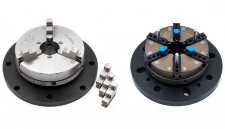
Hexagon’s Manufacturing Intelligence division has launched new high-quality chucks to enhance the measurement of cylindrical and rotationally symmetrical parts, one of the most common tasks undertaken on coordinate measuring machines (CMMs).
Hexagon’s Swift-Fix Chucks are designed to hold pieces in place with the help of either three or six jaws to ensure the best possible accessibility to the part. The highly accurate, self-centring and repeatable Swift-fix Chucks deploy consistent forces on all jaws and help users achieve the highest levels of precision and quality in the measurement process. A large and easy-to-handle adjustment range mean parts with various diameters can be mounted quickly. Depending on the application, parts can be held on the inner or outer diameter.
All three-jaw chucks contain jaws for inner and outer clamping to ensure the best possible positioning across a full range of applications. Six-jaw chucks are equipped with different position and stop pins, so that the clamping can be flexibly adjusted to changing applications.
Swift-Fix Chucks are manufactured from stainless steel or aluminium with additional ALTEF coating, making them completely resistant to corrosion, wear and scratches. In addition, all clamping jaws are vacuum hardened and polished. Hexagon’s choice of materials and attention to quality mean all chucks are easy to maintain and retain their high levels of precision and repeatability during long term use.
What is the most accurate way to check if a measuring tool works within its specifications? Guillaume Bull, product manager at Creaform, explains in this article.
When replacing old measuring equipment, it is common to validate that both the old device and the new device measure the same data and provide quality control (QC) with the same results. To do this, correlation tests are performed.
To facilitate and speed up the work, it is tempting to test a regularly manufactured part. After all, its specifications are well known. However, this choice of part may lead to a false diagnosis and an incorrect conclusion regarding the accuracy of the new measuring device.
Therefore, the most accurate way to check if a measuring tool works within its specifications is to use a calibrated artefact for which measurements have been previously validated and the data is traceable.
Using a common artefact for the old device and the new device helps to minimize the variables that can influence the correlation tests. Among these variables, which will induce measurement differences, are the extraction methods that are different from one technology to another, the alignment methods that are rarely the same, software that does not process or calculate data in the same way, the setups that are generally different depending on the technologies, and the environment that, if not maintained exactly the same, will greatly influence the measurements.
Using a calibrated and traceable artefact enables operators to validate that both devices work within their specifications. As a result, if the measurements taken on this calibrated artefact give the right value, we will know for sure that the measuring devices work properly.
Scenario
A manufacturing company working in the automotive industry wants to replace its CMM with a 3D scanner. In order to validate the new equipment, a correlation test is performed between the two devices—the old and the new. When the two measurements are compared, there is a difference; the instruments do not correlate with each other. Why? Should we not get the same measurement on both instruments? What is causing this difference? Since we know that the old equipment has been accurate historically, should we conclude that the new equipment has an accuracy issue?
When testing for correlations between two types of equipment (i.e., comparing the measurements obtained on the same part with two instruments), there are many variables that can induce errors in the measurements. These variables include extraction and alignment methods, software calculation, setup, and environment.
Extraction Methods
We measure the same part, but we do not extract the same points with one measuring tool as we do with the other tool. The consequence is a difference in measurement due to the imperfection of the geometry of the part. Indeed, when we probe a surface plan by taking a point at the four corners, this method does not consider the surface defaults of the plan. Conversely, if we scan this plan, we measure the entire surface and get the flatness. Therefore, if the surface has a slight curve, the scanned plan might be misaligned compared to the probed plan. Thus, there will be a difference in measurement between the two methods.
Alignment Methods
We measure the same part, but we use two different methods of alignment. The consequence is a slight difference in the alignment method, which can lead, due to leverage, to large deviations at the other end of the part. Even if the same method of alignment is used, as mentioned above, a difference in the extraction method of the features used in the alignment can lead to a misalignment of the part. The positioning values are based on the alignment, which must not differ from one instrument to another, neither in the construction method, nor in the way it is measured.
Software Computation
We measure the same part, but we use different software that does not use the same algorithms for data processing. The consequence is a difference in the calculation of a feature from the software, even though the measured data is the same. The more complex the construction of the measurement is, the more likely it is to have deviations between calculations.
We measure the same part, but we do not have the same setup on both instruments. The consequence is different measurements of this same part. For example, a part of large dimensions is measured on a CMM. The marble on which the part is placed has an excellent flatness (30 microns). The same part is then measured with a 3D scanning system. But the surface on which the part is put has a different flatness (800 microns). As a result, the part twists and deforms slightly when placed on the second marble. Although the same part is measured, the two setups give different measurements because the support surfaces have different degrees of flatness.
Environment
We measure the same part but under different conditions. The consequence is a difference in the measurements. Indeed, if we measure an aluminium part of one meter on a CMM at an ambient temperature of 20 deg C and we measure the exact same part at 25 deg C, then the difference in temperature will result in a lengthening of the part by 115 microns at 25 deg C.
Common Artefact
It is crucial for quality control to minimize these different variables that could lead to correlation errors. The easiest way is to use, on both instruments, a common artefact for which measurements have been previously validated and the data is traceable.
Artefacts have the distinguishing characteristics of being calibrated and traceable. All features have been previously measured and verified in a laboratory, eliminating any doubt and uncertainty regarding measurements.
A value commonly obtained with a traditional measuring instrument is not a reference value that can be relied upon 100%. The reason for this is that equipment is not an artefact. There is always uncertainty associated with any measuring instrument. Therefore, the verification, validation, or qualification of a measuring instrument cannot be done with any part for which dimensions have not been previously validated.
The only way to certify that a measuring tool works within its specifications is to compare it with an artefact whose dimensions are calibrated in a known laboratory. Only an artefact makes it possible to correlate measurements between equipment because only an artefact can subtract all the variables that could interfere with the measurement. Thanks to an artefact, there is no doubt; the equipment measures accurately.
If two devices get the same measurement with an artefact, but do not correlate on a specific part, then the difference is not attributable to the instruments. Rather, it will result from measurement processes that will need to be checked and scrutinized further to obtain the desired measurement.
The manufacturing industry has changed dramatically in the last 40 years. Jamco Aerospace Inc. recognised these changes and realised how critical it is to incorporate advanced quality inspection equipment into their manufacturing processes to stay competitive. They use two scanning CMMs (coordinate measuring machines) from Carl Zeiss Industrial Metrology (IMT) to ensure the precision of these processes every step of the way.
Jamco Aerospace is a manufacturer of complex, structural components typically used in the aerospace industry. Ninety-five percent of their orders come from the aerospace industry, with the remaining five percent coming from the ground transportation industry. The company is a full-service machining and airframe sub-assembly facility. Some of their larger customers include Northrop Grumman, Boeing, Spirit AeroSystems, and the US government.
In 2006 Jamco decided they needed more efficient quality inspection equipment to stay competitive in their industry and to comply with their recent ISO 9001/AS 9100, Rev. B certifications that require significant process documentation. Their touch-trigger CMM and manual gauges were no longer effective and the CMM’s software had also presented some programming challenges. They needed a new CMM that was comparable in size to their previous CMM but with better measuring technology.
“I have been involved in this business for over 40 years and the manufacturing base in the US has grown increasingly smaller and more competitive,” says Dr. Jack Lee, CEO of Jamco. “The scanning inspection technology is spreading fast and I believe the key is to improve quality throughout the entire manufacturing process, otherwise the final inspection is completely worthless.”
Technical Specification Fulfilled
Ronald Lee measuring main landing gear rib on the MMZ 20/50/15.
After an in-depth review, Jamco decided that a Carl Zeiss CONTURA G2 10/21/6 VAST XXT RDS with scanning technology was the best fit for their inspections. The CONTURA G2 10/21/6 is robust and the right size for their parts. The VAST XXT RDS articulating probe is designed for measuring small features and lots of angles, and can reach 20,736 positions in 2.5 degree increments. The scanning technology allows them to get much more information in a shorter amount of time than with their previous touch-trigger CMM, a feature that brings down manufacturing costs by improving efficiency.
Typical parts for Jamco are structural bulkheads or fittings used in aircraft which they measure on the CONTURA G2 for in-process and final inspection. Parts are inspected on the CMM after any initial finishing processes, before moving on to turning or milling processes followed by a second inspection. A final inspection is done after all processes or assembly are completed. The increased efficiency resulted in more orders over the years although most of their parts require 100 percent inspection. As the number of parts and orders grew, the company knew it would need an additional CMM.
They liked the CONTURA system with the VAST XXT RDS articulating probe but wanted a larger machine to more efficiently handle larger aerospace parts such as bulkheads, longerons, ribs, webs and frames, while keeping the same CALYPSO software and ZEISS quality. In 2011 they purchased a large gantry CMM, an MMZ 20/50/15 which could not only measure larger parts, but also large lot sizes of smaller parts.
Jamco appreciates the simplicity and user-friendliness of CALYPSO software. “Once you know what to look for it is pretty straight forward,” says Ronald Lee, Quality Control Manager at Jamco. “If an operator is unsure how to set up a part, the software shows multiple part views to make the process easier. And programming from CAD models with CALYPSO is a lot easier due to the integrated assistant that helps you select the measuring references so there is no difficult code or text editing. This allows you to spend more time measuring than programming, unlike with our previous metrology software.”
Increased Efficiency
The ZEISS systems have helped Jamco gain more customers with their improved quality inspection accuracy and efficiency. The CMMs also allow them reach their targeted tolerances that are all within 5 ten-thousandths of an inch. Their touch-trigger CMM collected about 100 points in 2 to 3 hours while the ZEISS scanning CMMs gather about 1000 points in just 1 to 2 minutes. Jamco currently measures approximately 30 parts a day. Typical parts are around 12 inches long and have a number of critical features requiring 30- 40 minute inspection programs. Efficiency is also increased because operators can multi-task while inspections are running. For larger orders of about 40 parts, they like to use the AutoRun feature so entire lots of parts can be inspected automatically.
The ZEISS systems have given Jamco the confidence in their ability to do more inspections and projects, and to measure bigger parts. The ZEISS MMZ machine effectively handles the larger parts, but it also inspects a pallet of smaller parts at once instead of having to do a series of measurements. “Quality assurance throughout all of our manufacturing processes has brought new confidence to us and our customers,” states Dr. Lee.
Real-time data analysis is playing an increasingly critical role in improving overall productivity and manufacturing competitiveness. Here’s how the metalworking sector, through advances in metrology solutions, can create a smarter manufacturing environment that is simple to manage and deploy. Article by Hexagon Manufacturing Intelligence.
In today’s business climate, it is of paramount importance to reach consistently high levels of productivity, quality and cost-effectiveness.
For this reason, metalworking companies are harnessing new data-driven technologies to enhance and automate their design, production and inspection processes. And the change is taking place beyond sectors that are traditionally highly sensitive to quality, such as aerospace and automotive.
As today’s coordinate measuring machines (CMM) and their associated sensors and software become much faster and more sophisticated at collecting and exchanging accurate inspection data, real-time data analysis is playing an increasingly critical role in improving overall productivity and manufacturing competitiveness.
Many manufacturers have already equipped their CMMs with multisensor technology that allows them to perform contact and optical non-contact inspection interchangeably, while quickly and efficiently capturing data that can be checked for accuracy against original CAD data.
Measurement data collection and analysis is supported by the Q-DAS statistical analysis software, which can be used to visualise measurement data in real-time and monitor them statistically. Q-DAS’s statistical process control (SPC) function systematically informs the CMM operator of any violations of SPC alarm criteria, enabling operators to take corrective action in the manufacturing process before generating expensive scrap. At the same time the software’s high flexibility allows users to adapt the recording and visualisation of data to specific tasks.
Using Real-time Analysis to Improve Performance
But now, manufacturers are going a step further to increase their productivity by addressing the challenges of improving machine utilisation, throughput and uptime. This is leading them to adopt asset management solutions, such as the HxGN SFx Asset Management software, to monitor the status of one or several CMMs in real-time. The growing use of asset management software is partly due to greater automation, which requires operators and managers to keep a close check on the performance of unattended machines. By using asset management to efficiently monitor the status of CMMs remotely, manufacturers can maximise machine usage.
Asset management can help the metalworking sector raise productivity across multiple applications, such as the measurement of rotor or stator lamination stacks. Rotor or stator lamination stacks are composed of individual electrical steel laminations and are typically inspected in pallets using image-processing (vision) sensors. Hexagon’s OPTIV multisensor and optical CMMs come equipped with a vision sensor as a standard and are commonly used to simplify the measurement of large or palletised flat parts such as rotor or stator laminations close to the shop floor. Equipped with handle workpiece palletising, the Hexagon OPTIV enables a fast and automated inspection process, even for large batches of small serial parts such as clutch discs and fine-blanked parts.
Because speed and accuracy are of the essence when inspecting rotor or stator lamination stacks, operators often need to manage multiple CMMs that are running pallet measurement routines unattended.
The OPTIV’s extended measurement range enables prepared interchangeable pallets to be supplied semi-automatically by a palletising robot, reducing standstill times and increasing inspection throughput.
Hexagon’s Inspect software, meanwhile, makes it simple for operators to set up one pallet and then prepare and launch the next on a separate CMM. Asset management software offers a simple dashboard view of machine availability, which allows operators to save additional time by identifying which CMM has spare capacity.
The right asset management tool also helps manufacturers optimise maintenance schedules and plan for a more efficient use of manufacturing resources. As a result, quality departments can shift from managing assets as a cost centre to creating value by optimising equipment profitability.
If, for example, a manufacturer needs to increase production to fulfil new orders for a customer, information from asset management systems makes it easy to identify where spare inspection capacity lies either locally or at another site.
Raising Your Equipment’s Overall Effectiveness
Successful asset management, however, depends on having instant access to actionable insights. Notifications about the performance and status of metrology assets, for example, need to be available in real-time. And all alerts should be readily customisable so that operators and managers receive the information that is pertinent to their role and in a format that is easy to access, understand and use.
For this reason, Hexagon has ensured its HxGN SFx Asset Management platform provides a simple, accurate way to monitor and analyse how key assets are performing via a centralised, user-friendly dashboard. It works equally well whether the machines being monitored are on a single site or in multiple factories around the world. And in addition to a having a dashboard view of each CMM’s uptime and downtime, it’s possible for operators to see how each machine is being used, all while working remotely on a mobile phone or a PC.
Having real-time insight into CMM performance not only enables operators and managers to schedule work efficiently and respond immediately to operator errors. They can also use data analysis to understand and manage the productivity of their assets over the long term and to calculate overall equipment effectiveness (OEE) either for a single CMM or for several CMMs, across multiple sites and over various periods of time. OEE is calculated using data for quality, which is based on a CMM’s success in completing measurement processes during the scheduled time, performance and availability. Gaining a thorough understanding of a CMM’s OEE makes it easier for manufacturers to reduce spending on maintenance while achieving better overall performance and efficiency.
Getting the Right Data with Versatile, Multisensor Systems
Any analysis is only as good as the data it relies on, which is why Hexagon is investing in ensuring all its systems deliver accurate, real-time, relevant data to where it is most needed. The HxGN SFx Asset Management solution is an important part of this strategy, but it is not the only element.
When it comes to inspection, the choice of CMM, sensors and supporting software for a given application clearly plays a pivotal role in determining the quality and quantity of data that manufacturers gather, and at what speed.
Multisensor CMMs have grown popular because of their versatility when capturing data at the varying levels of detail and speed required by different applications and materials.
Having the Vision to Improve Processes
Vision sensors remain a key inspection tool in the metalworking sector because they are adept at quickly and automatically measuring large volumes of intricate metal parts. Designed to capture surface detail swiftly, vision systems are particularly useful when dealing with high production rates.
A vision sensor with a high-resolution digital CMOS colour camera and a programmable motorised zoom lens, for example, can offer variable illumination in the form of a coaxial LED top light, LED back light and multi-segment LED ring light to provide high contrast illumination of complex surfaces and edges, all while quickly capturing data that informs the entire manufacturing process. Hexagon further enhanced vision sensor speed and performances when it launched a Large Field Of View vision sensor for its OPTIV CMMs. The new vision sensor provided a field of view that is approximately four times larger than the standard vision sensor on today’s OPTIV CMMs.
When it comes to using multisensor systems to measure metal workpieces, Hexagon’s OPTIV Dual Z helps increases batch measurement throughput by enabling optical and tactile sensors operating in restricted measuring volumes to automatically reach more measuring positions within a single measurement cycle.
Whether a manufacturer’s applications best suit a vision sensor, a laser sensor or a touch probe, Hexagon is focused on providing data-based solutions that easily integrate with existing and future systems to create a smarter manufacturing environment that is simple to manage and deploy.