Welding is a fabrication process that joins materials through coalescence, while cutting refers to the slicing of steel or other metals of different thickness through the use of different cutting equipment. And both are often used together in metalworking industries in manufacturing processes or for the production of outputs. Based on the product type, the welding and cutting equipment market can be further divided into five categories: arc welding equipment, gas welding equipment, MIG welders, plasma cutting equipment and others. While from the perspective of the end-user, the welding and cutting equipment market can be divided into another five categories: energy industry, shipbuilding industry, construction industry, automobile industry and others.
However, based on findings by Persistence Market Research, welding and cutting equipment are mostly deployed by the energy, automotive and construction industries as of now. And due to the rapid growth of industry 4.0, demand for welding and cutting equipment has increased globally. In particular, Asia-Pacific has risen up as the largest market for welding and cutting equipment, followed by North America and Europe and China and India are the key countries for the growth of the industry due to the high industrial growth rate, high growth rate in the construction sector and high growth rate of automotive industry in both countries. In fact, China’s economy is expected to continue growing by 7.8 percent and as of 2012, China has emerged as the largest steel nation globally. Meanwhile, countries that are part of the BRIC group (Brazil, Russia, India, and China) have also been highlighted as fast growing regions for the welding and cutting market.
Overall, the market is projected to grow at a substantial rate through 2020 due to increasing demand from the energy, automotive and construction industries. But market growth is also constrained by a decreased growth of the ship building, aerospace and defense industries. Key players in the industry include Illinois Tool Works Inc., Lincoln Electric Holdings Inc., Victor Technologies International Inc., Colfax Corp., ESAB, Panasonic Corp., Sonics & Materials Inc., Charter International Ltd. and Denyo Co. Ltd.
Lasers have been employed in a variety of welding applications for many years. And, as laser technology further develops and diversifies, its uses in welding continue to expand. This article by Coherent provides an overview of high power lasers in keyhole welding.
Most traditional (non-laser) welding techniques currently in use are variations of arc welding. In these methods, two pieces of metal are first brought into contact or close physical proximity. The edges of the pieces may have been shaped to facilitate their joining. A high voltage is established between an electrode and the contact region, creating an arc which melts the material (or, in some cases an additional filler material or the electrode itself). The melted material fills any gap between the workpieces, or overlays them, and then solidifies to join the parts.
The primary advantage of most arc welding methods is their relatively low cost, particularly in terms of the capital equipment expenditure. Furthermore, arc welding techniques are well understood and widely employed, and standards for producing and testing them are well established, so there’s not much of a learning curve in bringing these processes on line.
The major disadvantages of arc welding mostly derive from subjecting parts to high heat. This can result in microstructures in the melted material that yield poor strength in the weld joint, and a relatively large heat affected zone in the material adjacent to the weld. Additionally, the parameters of the arc are influenced by the local electric field, and can therefore not be set independently.
Laser Keyhole Welding
Most laser welding techniques can be classified into two basic categories, “keyhole” and “conduction mode” welding. Both of these welding modes are capable of being performed autogenously, that is, without filler metal, as well as with filler, if so desired.
Keyhole, or deep penetration welding, is commonly encountered when welding thicker materials at high laser powers. In keyhole welding, the laser is focused so as to achieve a very high power density at the work piece. At the focus of the laser beam, the metal actually vaporises, opening up a blind hole (the keyhole) within the molten metal pool. Vapour pressure holds back the surrounding molten metal and keeps this hole open during the process. The laser power is mainly absorbed at the vapour melt boundary and the keyhole walls. The focused laser beam and the keyhole continuously move along the welding path. At the front of the keyhole, new material is molten, and at the back, it resolidifies to become the welded joint.
The small size of the keyhole region results in a precise, narrow fusion zone, with a high aspect ratio (depth to width) as compared to arc welding methods. Furthermore, the highly localised application of heat means that bulk of the work piece acts as an effective heat sink so the weld region heats up and cools down rapidly. This minimises the size of the heat affected zone, and reduces grain growth. Thus, the laser can generally produce stronger joints than arc welding, which is one of its primary benefits.
Laser welding also offers greater flexibility than arc welding, since it is compatible with an extremely broad range of materials, including carbon steel, high strength steel, stainless steel, titanium, aluminium, and precious metals. It can also be used to join dissimilar materials, as differences in material melting temperatures and heat conduction are of minor importance in the process.
In addition, laser welding delivers significant cost advantages over traditional methods, when all the process steps are considered. In particular, the precise application of heat minimises distortion in the weld and overall part, thus eliminating the need for post processing in many cases. Plus, the ability to project the laser beam over relatively long distances with essentially no power loss makes it easy to integrate laser welding with other production processes, and lends itself well to integration with manufacturing robotics. Last, but not least, new product configurations with reduced flange sizes can be realized, which is critical for light weight vehicles in the automotive industry.
Fibre Lasers for Welding
Modern CO2 and fibre lasers easily deliver the beam parameters and power requirements for keyhole welding. Since almost all metals become increasingly absorptive at shorter wavelengths, process efficiency is enhanced at the shorter fibre laser wavelength of ~1 μm, as compared to CO2 laser wavelength of 10.6 μm.
Fibre lasers, in particular, match the requirements of keyhole welding extremely well. They typically offer output powers in the range of 500 W to 10 kW, and can readily achieve focused spot sizes in the necessary range between 40 μm and 800 μm, even at relatively large working distances. From a practical standpoint, the use of beam delivery fibre expands integration options and facilitates the use of the laser in the manufacturing environment. Finally, the high reliability, excellent uptime and favourable cost of ownership characteristics of fiber lasers make them an economically viable and attractive choice for production welding applications.
There are currently several manufacturers of high power fibre lasers for welding and other materials processing applications. Coherent | Rofin fibre lasers, for example, can deliver a combination of performance, reliability, ease of integration and cost characteristics that is optimum for welding and other materials processing applications. To understand how this is achieved, it’s useful to examine some of the design and construction details of these lasers.
The drawing shows the main elements of the fibre laser oscillator employed by Coherent | Rofin. The laser resonator is formed by a large mode area (LMA), Yb-doped, double clad optical fibre and fibre Bragg gratings for resonator mirrors. This is pumped from each end by a series of diode laser pump modules, whose outputs are fibre coupled into the gain fibre.
Coherent | Rofin fibre laser oscillator schematic, including 12 diode laser pump modules, and 6×1 fibre coupling modules which inject pump light into the gain fibre, and allow efficient extraction of the laser output.
Based on this design, one set of pumps and gain fibre can produce output powers of up to 3kW. The output from up to four of these single mode fibre laser units can then be combined into one multimode fibre to achieve powers of up to 10kW. Alternately, the “standard” cabinet supports splitting the output from a single fibre laser into four separate fibres through the use of the integrated fibre-to-fibre switches.
Thus, this modular construction approach allows Coherent | Rofin to offer several options in terms of output power, delivery fibre diameter, and beam parameter product. The benefit is the ability to readily adapt the laser beam characteristics to precisely match the exact requirements of a specific process.
Some users have experienced fibre laser damage or process inconsistencies caused by back reflections when processing highly reflective metals, such as copper and brass. Coherent | Rofin lasers utilise an optimised power generation and delivery technology, as well as sensors at different positions within the system, to protect laser components from such damage. These safeguards eliminate the problem of back reflections, and allow reliable welding of brass, aluminium and copper without any concern for damaging the laser.
Of course, the fibre laser is just one part of the entire welding system, which also includes a beam focusing welding head, as well as control electronics. In addition to fibre lasers, Coherent | Rofin also offers beam delivery components which mount into customers’ machines. These can be fixed optics or complete, integrated scanning solutions, which include control of all relevant laser parameters, to fully optimize the welding process. Moreover, these integrated solutions often feature fast and flexible beam scanning technology which allows rapid beam movement from one welding contour to the next. This increases the productivity of a laser processing system enormously.
Poor concentration and fatigue is sometime you will never see with robots, which have always been seen by their human counterparts as reliable and indispensable “colleagues”. Contributed by Messe Dusseldorf
Robots are now increasingly handling the welding, bending, cutting, separation, transfer and storage of pipes and tubes. Thanks to artificial intelligence and machine learning, robots are set to become even more flexible and will eventually replace purely repetitive robots altogether.
Picture this—you turn up at work in the morning, and the first thing you do is switch on the television. It does not seem very appropriate at first sight. But this is precisely what is being turned into reality with the camera-controlled and fully electric manufacturing cell from transfluid—the element which is right at the heart of a smart tube forming system. What you can see “flickering” on a large screen is not the latest news bulletin, but valuable details about the energy consumption, process capacity value and quantity of the tubes formed up to now.
Robots As An Important Module
Robots are an important module at the transfluid tube forming centre and are used in the production of air conditioning lines. As well as a camera monitoring system, the plant has a magazine, a 4-axle handling system, two combination machines for tube forming purposes, a bending machine, a chamfering unit, a dot-matrix printer and two robots.
Before bending can start, one side of a tube is always handled in combination with a tube forming machine, while the other side is chiplessly cut after the bending process and is then also formed.
Should this be required, the robot subsequently holds the tube into a deburring device. “Both ends can be visually monitored via a camera. Alternatively, the robot holds the tube into a labelling unit where it can then be marked at all the required points—and in fact completely without any clamping device,” said Stefanie Flaeper, managing director of transfluid.
100 Percent Quality
Using a forming system with a rotary table, it would then be possible to join two tubes together with a flange. For the manufacturing process this means maximum safety, a high yield and documented quality —while information is provided on a large screen as a nice side-effect.
Robots have definitely proved their worth in pipe and tube forming. Ms Flaeper emphasised that they “ensure controlled handling” because a robot is, after all, ideally suited for the manufacturing of bent components.
She added,“On the other hand, they tend to be of lesser significance in the handling of long, straight tubes and pipes. Linear systems are faster for this purpose.” Robots are particularly widespread in machining, “because this involves either complex handling or manipulating heavy parts.”
Use In Welding
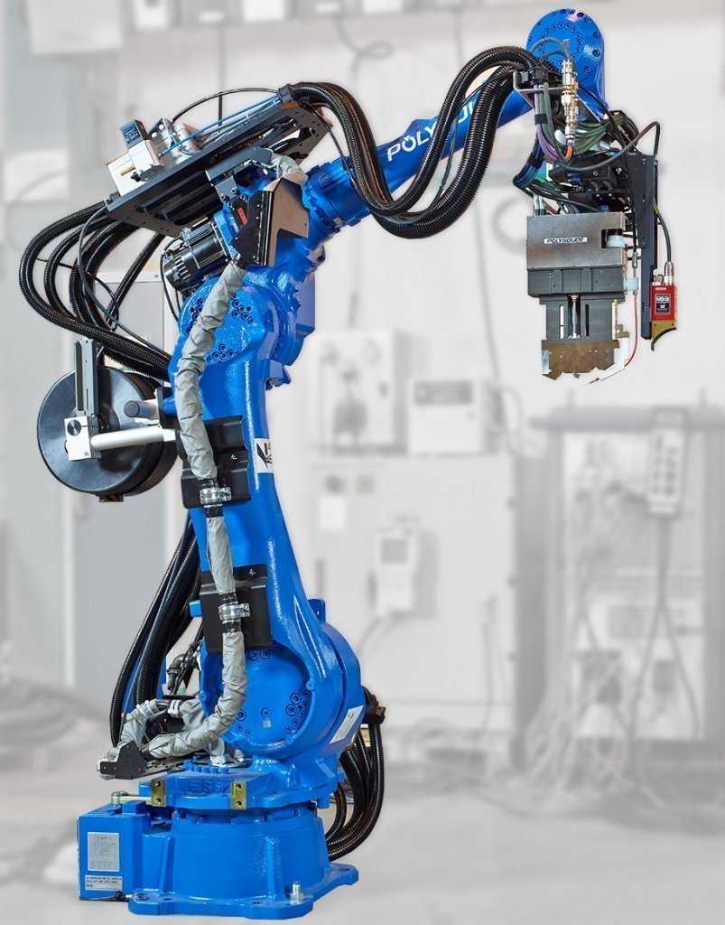
For Polysoude and its customers, robots are a good supplement to conventional automation solutions. A robot makes it possible to guide the torch along the pipes themselves in manual tungsten inert gas (TIG) welding, even where there is not much space. It also ensures “a high-quality seam thanks to the precision and reproducibility of movements in complex geometries,” said Hans-Peter Mariner, managing director of Polysoude.
Robots are generally very widespread in welding, but not particularly in TIG welding. According to Mr Mariner, TIG is used “almost never in conjunction with narrow gap welding or the welding of pipe-floor joints.” This is due to legal requirements which include, for instance, a shielded zone without user access—unlike conventional automation solutions. The company, however, allows the use of robots in TIG welding.
Robots And Nuclear Fusion
The essential criterion for choosing a specific type of robot is the level of precision which Mr Mariner states “is a matter of the TIG welding itself, even under full load, within a range of five to 10 mm.” Furthermore, he added that it was important for a robot to be easy to program and to have sensors, especially for smart tracking purposes.
The use of robots in TIG welding has achieved a certain amount of fame in one of the most ambitious projects in the world, called the International Thermonuclear Experimental Reactor (ITER). The project is to prove that nuclear fusion as an energy source can be used for electric power production without major carbon emissions. 35 countries are participating in the design of the planned Tokamaks nuclear fusion chamber.
Welding Together Extremely Thick Walls
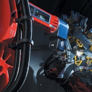
The company supplied a robotic welding system to the Italian engineering company Simic where they were used for the construction of radial plates for the ITER. The plates were made from stainless steel, each with a wall thickness of 100 mm, and welding together these parts turned out to be an extraordinary challenge. The work is currently performed onsite, in southern France, with major requirements in terms of bonding precision and quality.
Hot wire TIG narrow gap welding turned out to be the best choice for welding together such extremely thick parts. The tool carriers for narrow gap burners, such as robots and welding trolleys, have been adjusted to suit the target object in both size and geometry. Narrow gap TIG welding, incidentally, can also be applied for pieces up to 400 mm in wall thickness.
Reaching For The Stars
Naturally, reliability and quality are greatly prioritised on the ITER project which has been in progress at the Cadarache Nuclear Research Centre in France since 2007. The Tokamaks chamber, which is surrounded by super-conductive magnets, is to serve as the place where the hydrogen isotopes deuterium and tritium are to be heated up to a temperature of 100million deg C, causing them to fuse. It’s a technology that reaches for the stars—quite literally, by seeking to imitate them. After all, it is nuclear fusion that enables the sun and the stars give off energy.
However, ITER has also drawn criticism, due to its immense expenses—estimated at over 15 billion euros (US$18.5 billion)—for one of the biggest building sites in Europe, coupled with a delay in completion. Advocates of the projects, on the other hand, see nuclear fusion above all as a highly efficient form of energy production, apparently generating 10 times as much in output. Moreover, it is considered to be an energy source without carbon emissions and virtually no radioactive waste. The first hydrogen plasma is expected to be produced around 2025. Robots, too, are helping towards the success of the ITER project.
Robots In Machine Processing
Sometimes it is the combination that matters. Twister, a bending system developed by Wafios, can even be used in pipe/hose combinations. To boost productivity, Wafios has linked the system to a robot from Kuka, and operation is simple.
Until recently, the focus has been mainly on handling processes where the demand on accuracy is relatively modest. Either the process chain included a processing tool with a specific element which compensated for inaccuracies —a polishing disc, grinding head or flexibly deflecting deburring spindle—or the issue of accuracy was more or less irrelevant. “Such handling processes are still often carried out by humans. However, due to increasing cost pressure, yet unchanging quality requirements or lack of human resources, they will be handled more and more by machines or automatically,” says Alexander Bailey, market segment manager, CNC/machining at Kuka Roboter.
China As A Future Market
It is a development which the company is prepared for. The general industry is growing very strongly, mainly outside Germany. “All you need to do is look at the electronics market which offers enormous potential for growth in automation,” said Mr Bay. Apparently, this is particularly true for Asia, and the focus on the general industry goes hand in hand with increasing internationalism.
Germany continues to be seen by the company as an important market for a robotic automation solutions. “However, we also believe that the big growth markets of the future are outside Germany and Europe. This is why we are focusing above all on Asia and, within Asia, on China, the country which—according to the International Federation of Robotics—has the biggest and fastest growing market for industrial robots.”
There are good reasons why the Middle Kingdom is considered to be the future market for robotics. It is already by far the biggest sales market in industrial robotics and is marked by extremely high growth rates. In three years’ time the International Federation of Robotics is expecting China’s annual sales of industrial robotics to rise to 160,000 items, which would then be nearly 40 per cent of all global sales.
Robots— Colleagues Of The Future
There can be no question that the use of robots already has enormous potential: Whenever the product quality is impacted by the workforce, robots have major potential. One important driver in the application of robots is considered to be the automotive industry.
And the end of this potential is still a long way off. Until now robots have mainly performed repetitive tasks, working at the same level of consistent precision and repeatability. “The requirements of the future will be different—especially in professional service robotics,” said Mr Bay. “If robots are to move into other areas, they will need to become more flexible, and this is where machine learning might help.”
Part of Industry 4.0
Robots are increasingly also entering Industry 4.0. Serving as flexible production elements, robots will be able to collect data in production and then exchange them with IT systems. “As a result,” said Mr Bay, “production routines will become even more efficient, and systems will be able to respond quickly to specific customer requests.”
Another trend is the simplification of programming. “This will include online connectivity for robots, enabling them, for instance, to import data from external systems, such as CAD,” said Ms Flaeper. It is apparently quite a challenge to use robots for very small production sizes—something which is still only possible to a limited extent.
Industrial & Private Environments
The company sees great future potential in the 3C, logistics and service/consumer robotics. Mr Bay also felt that robotics is increasingly moving from the highly organised sphere of industrial production into the more “chaotic” private environment. This is because artificial intelligence can help to prepare robotic systems for imponderables and changes.
Nevertheless, one thing is certain: “Robots will move closer to people, taking over even more tasks from humans and supporting them in carrying out certain difficult jobs,” said Ms Flaeper.
She posits an even more fascinating thought to ponder: “It would also be interesting if a robot could imitate the movements of a human being in a production process with a high level of accuracy, but without the need to be programmed.”
Stockholm, Sweden: Sandvik Materials Technology has announced its intention to sell its welding and stainless wire operations to further consolidate its product portfolio and improve its long term performance.
Automotive manufacturing, given its complexity and volumes, requires the use of efficient, high-volume processes which can guarantee productivity and quality. In practical terms, this can be translated in the need for effective performance-based welding solutions that deliver both speed and precision – the drivers behind the increasing use of lasers for cutting, welding and brazing. Alessio Cocchi – Comau Robotics Marketing Manager shares more on this.
Thanks to the implementation of a new line featuring robots, which was made possible by the collaboration between SIR, a system integrator based in Modena, and FCA Cento, production of new engine blocks for 3000cc V6 diesel engines is doubled. Contributed by Comau
Metromec Quartis R15 released by Wenzel Metromec has numerous added features. Additional functions in the work window “Feature data” display results directly, before the report is created at the end of the measurement program.
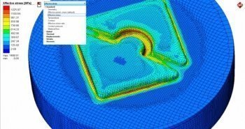
Simufact Forming 14 provides a graphical user interface that simplifies modelling and evaluation of simulation results. A new function is the pressure welding module which enables the simulation of joining processes by pressure and heat.
Commonly used in passenger cars, research is being carried out to make the laser processing of ultra-high strength steel sheets more economical. By Dr Andreas Weisheit and Dr Dirk Petring, Fraunhofer Institute for Laser Technology
Mobile phone manufacturers are grappling with the need to track smaller, and better, components, presenting challenges and opportunities for designs. Contributed by Panasonic.
A far cry from the bulky mobile phones of the early 2000s, today, a 0.25 x 0.125mm chip resistor is one of the most widely used components in mobile phone manufacturing.
It’s not news that the demand for smart phones, wearable devices and other personal electronics is increasing rapidly. In the case of mobile phones, more than 1.8 billion phones – inclusive of feature and smart phones – were manufactured in 2015, with the number projected to increase to two billion in 2020.
What is news, is that in order to meet rising consumer demands – smaller, thinner, longer battery life, higher performance – these highly complex electronic products require ever-shrinking components, requiring manufacturers to evolve and keep up with the ever-changing requirements of the industry.
Mobile phones are highly complex electronic products. Feature phones require between 600-800 components, while smart phones require upwards of 1,000. As higher functionality continues to be expected by consumers, the number of components ultimately increases year-on-year. But the demand for smaller and thinner devices and the need to balance longer battery life with higher performance also pose new challenges for devices manufacturers.
Printed Circuit Boards
Printed circuit boards eliminate the space challenge of complex wirings and moving parts that were commonplace with the point-to-point wiring that preceded them – without them, fitting a large number of interconnected electronic components into an ever-shrinking space would be impossible.
Today, a 0.25 x 0.125mm chip resistor is one of the most well-known components in mobile phone manufacturing.
During manufacturing, chip resistors are soldered onto circuit boards, with the solder being applied as a paste and shaped into the boards through screen printing, requiring a high level of accuracy despite its small size.
Surface Mount Technology
Another noteworthy innovation in the field is surface mount technology, which produces electric circuits through the direct mounting of components on the surface of printed circuit boards. The new technology is also evolving to increase the mounting/insertion rate and accuracy of increasingly miniscule components.
Surface mount technology has come a long way since it first emerged in the 1950s and 1960s , resulting in many advantages over their leaded predecessors in terms of manufacturability and performance. Surface mounting has also resulted in a reduction in labour cost and increasing productivity rates in the production of printed circuit boards, as process lends itself well to a high degree of mechanisation and mass production.
Chip Mounter Machines
One such company leading the charge towards more efficient manufacturing technologies and equipment is Panasonic. The electronics giant is still commonly known for its consumer electronics, when in fact, Panasonic today is on track to attain a 40 percent share in the chip mounter machine field in South East Asia.
Its newly opened Solution & Innovation Centres in Thailand, Indonesia and Vietnam therefore highlights the company’s highly-efficient manufacturing technologies and equipment. Tapping into Panasonic’s manufacturing know-how, the Solution & Innovation Centres showcase the company’s suite of manufacturing technologies such as auto-insertion and surface mount machines, designed specifically for the inserting and mounting of small electronic components on high-density printed circuit boards.
In addition to Panasonic’s latest chip mounter and welding machines, peripheral equipment from other partners, such as component tower and inspection machines, are also featured, with the synergy highlighting the importance of network compatibility and technological interconnectedness, and the contribution of interconnectivity to the success of Industry 4.0 and IoT-supported manufacturing. Seminar halls and conference rooms located within the centres also serve to showcase Panasonic’s factory automation technologies to its customers through technical seminars and events.
Trial Run
To experience actual manufacturing processes at the centres, such as circuit board printing and welding, customers are invited to bring their own materials and electronic components for a trial production ahead of any agreements with Panasonic.
Panasonic’s Solution & Innovation Centres are also present in Chicago, USA and Munich, Germany, with global expansion taking place in the near future and more centres in the pipeline, tying in with Panasonic’s expansion of its factory automation business globally.