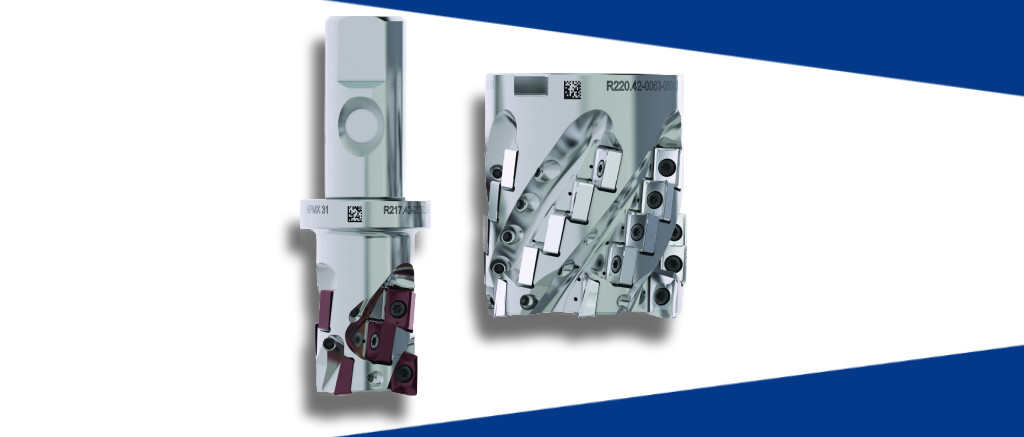
The new Seco LN4-11 Helical Milling Cutter provides up to three times longer tool life per edge and boosts productivity to achieve the lowest cost per part. The cutter ensures high material removal rates in applications requiring a helical milling cutter 32 – 63 mm in diameter.
Economical and user-friendly The LN4-11 provides shops several avenues to cut costs and improve profitability. Its adaptability to a variety of applications enables shops to reduce tooling inventories and costs. Operators simply change out the cutter’s inserts to go from one application the next. The tool’s front and helical insert pockets also eliminate the risk of incorrect insert placement to improve efficiency and reduce waste.
“The new Seco LN4-11 Helical Milling Cutter is the answer to the challenges shops face today,” said Seco Product Manager Magnus Engdahl. “It’s impossible to load the inserts of the cutter incorrectly, and every cutter body and insert feature an individual Seco Data Matrix code that provides access to cutting data and spare part tracking. It’s an excellent opportunity for shops to improve productivity and efficiency while overcoming the challenges created by lesser skilled operators.”
Four cutting edges for cost-effective milling The milling cutter has two different inserts. There are two cutting edges on the front inserts and four edges on the helix inserts. The design allows robust machining operations and aggressive material removal rates. Cost performance is enhanced, and tool life is improved. Inserts are available in a broad range of grades and geometries for a variety of operations and materials. The LN4-11 meets the demands of general engineering and automotive applications as well as those in the aerospace sector.
Each cutter’s individual Data Matrix code ensures easy access to all relevant tooling information including individual data metrics, cutting data, compatible products and spare parts.
In principle, machining large parts involves the same cutting action and chip formation process as for small or mid-size parts. However, large dimensions demand a specific approach to machining, and manufacturers need to plan technological processes and choose more effective cutting tools in order to produce heavy parts that take up a great deal of space. Article by Andrei Petrilin, Technical Manager, ISCAR.
Transporting a part inside a shop floor, mounting the part in a machine tool and clamping it properly, and machine setup are major challenges. Workholding massive and large parts is not an easy task, and often requires non-standard solutions. Machining large parts involves removing a lot of material that may cause significant deformations due to unrelieved stresses. Another factor, which leads to dimensional problems, is thermal expansion caused by heat generation during cutting: the large sizes make it much more sensitive comparing with “normal-in-size” workpieces. The necessity to remove a significant material stock requires appropriate chip evacuation to prevent the chip re-cutting, which negatively affects the applied cutting tools.
The key for overcoming the difficulties lies in technology, based on effective process planning and utilizing the most suitable machine tools, optimal workholding, and minimal part relocation. Single setup machining represents an absolute ideal for machining a large part, and producers from fields such as power generation, aerospace , railway, die and mold making, and heavy industry make every effort to approach this ideal. And cutting tools play a meaningful role towards reaching the target.
A distinct feature of these industries is their substantial consumption of large heavy-duty tools, mostly indexable, intended for productive removal of large quantities of material, especially in rough and semi-rough machining operations.
Large part manufacturers expect the same from cutting tools as any other producer using metal cutting technologies: excellent performance, good tool life, and high reliability. The latter two are especially essential because the large sizes lead to increased machining time, but replacing a worn tool in the middle of a pass and unpredictable breakage of the tool during cutting are totally unacceptable. In order to maximally meet the requirements of large part manufacturers, cutting tool producers provide various solutions, based on both standard and special designs. As a leading company in the cutting tool industry, ISCAR’s years of accumulated knowhow and experience have proved to be advantageous in developing efficient solutions to these challenges.
Figure 1
Heavy-Duty Facing
It is hard to machine a large part without face milling operations. Rough and fine machining of free and bounded planes and preparing datum surfaces require various indexable face mills. ISCAR’s standard face mills possess nominal diameters up to 315 mm (12″), while special tailor-made tools might feature higher values. The inserts are mounted in face mills and vary in cutting geometry as they are intended for machining different groups of material. Significant removal of machining stock by milling is primarily an issue for the production of large parts from steel and cast iron and, slightly less, from titanium and aluminum.
ISCAR’s line of standard face mills includes many tool families for large part manufacturing. HELITANG T465 features cutters with a 65° cutting edge angle and carrying tangentially clamped inserts. The robust design enables productive machining with a depth of cut up to 19 mm (.750″). The HELIDO 890 family features 89° face mills with lay-down square double-sided inserts (Fig. 1). These efficient mills, which are truly indispensable in milling a plane near the shoulder, offer an important economic advantage: the square inserts provide eight indexable cutting edges for depth of cut up to 9 mm (.354″).
Extended Flute, Extended Effect
Indexable extended flute “long-edge” cutters are considered as winning tools for productive rough milling. In manufacturing large parts, they excel in machining deep shoulders and cavities. Extended flute cutters are also utilised in “edging” – milling wide straight edges, an operation which is common for various processes from machining slabs and ingots to primary contouring.
Figure 2
ISCAR’s line of indexable extended flute cutters varies in design configuration, integrating a shank- and arbour-type mounting method and a radial or tangential insert clamping principle. These tools work in hard cutting conditions and experience significant mechanical and thermal loading. Intensive material removal requires the appropriate volume of a tool chip gullet to ensure effective chip evacuation. The situation can be dramatically improved by applying ISCAR’s extended flute cutters carrying inserts with chip splitting geometry to divide a wide chip into small segments. As a result, cutting forces are reduced, vibrations are stabilized, and thermal problems are eased.
Although 90° tools are the most commonly used cutters, machining large parts also requires rough milling of inclined and 3D surfaces, for which ISCAR provides a family of tapered extended flute cutters with 22.5°- 75°cutting edge angles. In some cases, particularly in die and mold making, combined rough and shoulder milling is needed. The DROPMILL 3 extended flute ball nose mills were designed specifically for such applications.
Producing large-size aerospace components from hard-to-machine titanium alloys is an extremely metal-intensive process with a significant buy-to-fly ratio. The eventual weight of a part may be only 10%, or even less, of the original weight of a workpiece. The XQUAD extended flute cutter family, one of ISCAR’s newest products, is intended for high-efficiency milling of deep cavities and wide edges in titanium parts. These tools (Fig. 2) are suitable for machining with high pressure coolant supply, which significantly increases productivity and improves tool life. The tools have already proved themselves: for example, component producers have achieved a 700-1000 cm³/min (43-61 in³/min) metal removal rate (MRR) by using an 80 mm (3”) diameter XQUAD cutter.
In railway engineering, combine mills are used to ensure simultaneous machining on several areas of the part. These mills incorporate an extended cutting edge, formed by a set of successively mounted indexable inserts.
Figure 3
Productive fast runner
High efficiency machining by indexable extended flute cutters and large-diameter face mills can be likened to the work of a heavy excavator digging sand with a big bucket. The full sand bucket, operated by a powerful engine, slowly moves a large volume of waste material. At the same time, there is an alternative method for efficient excavating. Imagine a more compact track trencher with a rapidly moving digging chain. Each link of the chain removes a small volume of sand but does it fast. In metal cutting, this trencher is a high feed mill, which machines at shallow depths of cut but with a feed per tooth that is far higher than the usual rates – millimetres as opposed to tenths of millimetres.
Fast feed mills are applied mainly to rough machining of plane faces, cavities and 3D surfaces (Fig. 3). These tools are more typical in manufacturing large parts from steel and cast iron, although high feed milling (HFM) titanium and high temperature alloys is not uncommon today.
ISCAR has a wide choice of fast feed mill families, intended for cutting various materials in different applications. The “world” of ISCAR’s HFM cutters encompasses tool families in diameter ranges of up to 160 mm (6.3″) that can meet the requirements of the most demanding customer.
High feed milling requires machine tools with high-speed feed drive. Large part manufacturers often have heavy, powerful but slow machines that are not suitable for high feed face milling. For these customers, ISCAR developed moderate feed (MF) cutters. Compared with fast feed mills, moderate feed cutters feature a higher cutting edge angle; they move slower but machine at higher depths and need more power to make them suitable for applying to heavy machines.
Large parts are often made from difficult-to-cut materials such as hard and high wear-resistant steel or cast iron. The welded part structure and the process of repairing worn parts by spraying fillers or soldering, add materials that are not easy-to-machine either. High speed milling (HSM) resolves these issues. Originally applied in die and mold making, high speed milling was developed as a productive method of milling hard steel that led to decreasing a part relocation, lessening setup, minimizing manual finish and polish, and, as a result, reducing cycle time. High speed milling features a small-in-diameter tool that rotates at high speed and mills material at shallow, light cuts.
The most suitable HSM tool is a solid carbide endmill and ISCAR’s MULTI-MASTER family of assembled endmills, which carry cemented carbide exchangeable heads, also represents a viable option. ISCAR’s line of solid carbide endmills offers various multi-flute tools in diameters of up to 20 mm (.750″), intended for high speed milling materials with hardness up to HRC 70. Decreasing machining allowances due to the production of more accurate workpieces for large parts, for example by using precise casting or molding, opens up new opportunities for high speed milling.
Figure 4
Exchangeable Heads Change The Dynamics
In many cases, manufacturing large parts is small-volume and even individual. In this context, minimizing machine tool downtime has critical importance. Intelligent process planning to considerably reduce setup time can help solve this issue. Each time a worn cutter is replaced, additional measuring and CNC program corrections are required, which increases downtime.
ISCAR’s families of rotating assembled tools with exchangeable heads – MULTI-MASTER mills and SUMOCHAM drills (Fig. 4) – enable substantial decreases in downtime. Face contact between a head and a tool body ensures that the head overhang is within strict tolerance limits, resulting in high dimensional repeatability of the assembly. Replacing a worn head does not require additional setup operations or removal of the tool from a machine.
Figure 5
U-Turn With Turn Milling
Turn milling, which is the method of cutting a rotating workpiece by a face milling cutter, is a good option for machining heavy rotary parts. In turning, the cutting speed is a function of rotating velocity. If the main drive of a machine tool does not allow rotation of large masses with the required velocity, due to limitations of its working characteristics, then the cutting speed is far from the optimal range and turning performance will be low. Turn milling offers an effective solution to the above difficulties. When turning large eccentric parts like crankshafts, off-centre masses of the parts cause unbalanced forces that adversely affect performance. Turn milling features low rotary velocity of a part, which prevents this negative effect (Fig. 5).
The majority of ISCAR’s indexable face-milling cutters are suitable for turn milling. The success of their application depends on cutter positioning with respect to the machined part, choosing optimal geometry of inserts, and cutting data calculation. ISCAR’s specialists in the field studied turn-milling kinematics and developed an appropriate methodology for defining these parameters.
Reliable Performance
Machining large parts is a time-consuming process, during which the tools cut material for a long period, and this means that tool reliability, stability, and predictable wear are high priority issues. A sudden tool failure may seriously damage the part and even cause its rejection. A cutting tool manufacturer has a limited choice of instruments for improving reliability, including advanced tool design, progressive cutting material, and technological development. Effective utilization of these instruments is the key to successful large part machining and ISCAR’s recently-introduced range of new tools and carbide grades provides that key.
What is the next stage in the evolution of ISO turning? Ever smaller, ever lighter – many developments across vastly different industries are driven by the trend towards miniaturisation or lightweight construction. For mechanical engineering and suppliers, this results in entirely new challenges for metal machining. Article by Walter AG.
Application example – impeller: The surfaces produced using the HIPIMS PVD process are extremely smooth. This reduces build-up on the cutting edge and the generation of heat thanks due to reduced friction. (Image Walter AG)
Even though it is most apparent in the field of communication and entertainment electronics, the trend towards miniaturisation is shaping many areas of industry: From the medical industry, to the automotive industry, right through to aircraft construction. For producers, this means that they must adapt their processes to increasing demands for dimensional stability and surface quality or even switch to new materials.
Particularly hard, but also particularly tough, materials (such as Inconel 718DA with 42 HRC in the aerospace industry or Ti-6Al-4V in the medical and food industry) have complex requirements for the indexable inserts during ISO turning. This is because tough materials have a high tendency for adhesion, especially when they have a high nickel content (Ni). This results in the chips sticking to the cutting edge forming a build-up on the cutting edge. The dimensional stability and the surface quality suffer. The fact that cutting edges become worn relatively quickly had to be accepted until now, especially in the case of high-strength materials.
During ISO turning operations with high to medium depths of cut, the CVD-coated indexable inserts which have previously dominated the market offer good to outstanding possibilities. However, they reach their limits in machining applications such as finishing and fine finishing, particularly where precision and tool life are concerned. This is where Walter’s machining specialists identified major potential for optimisation.
Gerd Kußmaul, Senior Turning Product Manager at Walter, describes the concept behind the new HIPIMS PVD-coated indexable inserts as follows: “Even if the fine finishing and finishing of ISO M, ISO S, ISO P and ISO N materials with the highest requirements for surface quality are still special or niche applications at the moment, we see great potential here due to dynamic growth in the market right now. Fine finishing involves turning operations which are designed to achieve a consistently good surface quality. This is in the range from Rz 1.6 µm to Rz 6.3 µm – throughout the entire tool life of the indexable insert. This is why for some time Walter has been looking for geometries and cutting tool materials that achieve this with process reliability. The new PVD HIPIMS coatings demonstrate ideal properties for achieving this with their extremely smooth surface and great layer adhesion on sharp cutting edges.”
Innovative Coating Technology To Ensure Best Performance
Walter is one of few indexable insert manufacturers to perform the new PVD HIPIMS process in-house and continuously expand the application possibilities with a dedicated PVD development team. HIPIMS stands for “High Power Impulse Magnetron Sputtering”. In contrast to conventional DC sputtering processes, the HIPIMS process involves subjecting the targets to short pulses of a few kilowatts of power. This produces a plasma density of 1013 ions per cubic centimetre, which have a high content of target metal ions. The bonding of the layers to the substrate is also excellent.
Indexable inserts with extremely sharp geometries, such as the FN2 or the MN2 “Aluminium geometry”, benefit from this coating process in particular because extremely stable cutting edges are produced. Even under high loads, the layers do not chip off and the cutting edges do not break away. In addition, the high level of edge stability ensures that the cutting edge is not only subjected to less wear, but that this wear also occurs evenly. The even wearing ensures dimensional stability and defined surface quality, even right up to the end of the tool life. Another advantage of the HIPIMS process is that the coatings are extremely smooth making them ideal for machining sticky aluminium alloys, for example; materials which would otherwise stick to the cutting edge during machining now reliably glide over it. Typical forms of wear such as built-up edges or significant flank face wear caused by chemical and physical reactions with the adhering material rarely occur. Walter’s new HIPIMS PVD grades WNN10 and WSM01 also have a long tool life.
Finishing of Inconel 718 DA – 40 HRC with Vc: 80 m/min: With identical cutting data, the new HIPIMS PVD-coated DCGT11T304-FM2 WSM01 indexable insert increased the tool life from nine minutes to 18 minutes compared to the DCGT11T304-PF2 WXN10 indexable insert and consistently achieved a surface quality between Rz 2 and Rz 4 μm throughout the entire tool life. (Image: Walter AG)
Long Tool Life, Increased Machining Volumes
Since the launch in 2017, sales for the HIPIMS PVD indexable inserts has grown consistently. Walter is pleased with the positive response from many customers who have already made the change from the previous WXN10 or WK1 cutting tool materials to the PVD-coated WNN10 or WSM01 indexable inserts. Walter Product Manager Gerd Kußmaul reports: “There must be good reasons to change the cutting tool material in established processes. Among other factors, the outstanding results achieved by the new HIPIMS grades with regard to tool life and surface quality speak in their favour. This is clear to see from the comparative tests. For instance, when performing finishing operations on tool steel X40CRMoV5-1 (DIN1.2344) with 54 HRC, it was possible to increase the tool life by 275 percent. And the surface value of Ra 0.8 µm was achieved throughout the entire tool life with process reliability. Another application was finishing Inconel 718DA at a cutting speed of 80 m/min, with the new grade WSM01 and achieving a cutting time of 18 minutes. In comparison to this, the previous grade WXN10 was only able to achieve nine minutes. In addition, a consistently good surface quality between Rz 2 µm and Rz 4 µm was achieved throughout the entire tool life.”
Process Reliability And Cost Reduction
Walter’s new HIPIMS PVD indexable inserts have potential to be effectively used anywhere that maximum precision, surface quality and process reliability are required. At the same time, these inserts have a positive effect on costs because the HIPIMS PVD coating, in conjunction with a carbide substrate, results in a cutting tool material that offers a long tool life with consistently high machining quality right to the very end. This is especially true for difficult machining steps such as fine finishing and for very sticky materials such as aluminium alloys with a high silicon content. In fact, the tool life and surface quality differences compared to previous indexable inserts are so significant that they result in a noticeable cost reduction in production.
In comparative tests, Walter achieved a 73 percent increase in tool life quantity with the WNN10 indexable inserts (compared with previous cutting tool materials) for machining red bronze. (Image: Walter AG)
Optimal Surface Quality When Finishing And Roughing
Walter developed the new WNN10 grade for finishing and roughing of ISO N materials such as aluminium-, copper- and magnesium-based alloys. The indexable inserts are available in two geometries. The FN2 geometry with 18° rake angle is ideal for finishing operations and for long, thin shafts that tend to vibrate. The MN2 geometry with 25° rake angle can be used universally for medium machining of non-ferrous metals.
The new grade WSM01 is available in the FM2, MM4 and MN2 positive geometries and in the MS3, NMS and NRS negative geometries. Its main area of application is finishing and medium machining of nickel- and cobalt-based high-temperature alloys (ISO S) but it is also used with stainless materials (ISO M) such as austenitic stainless steel 1.4301, 1.4404 or duplex steel 1.4462. It is used, for example, for machining engine components in the aerospace industry or for producing surgical instruments in the medical industry. Its applications also include machining stainless steels or hard turning tool steel such as X40CrMoV5-1 with 54 HRC. To summarise, it can be said that the new HIPIMS PVD grade WSM01 is the ideal solution for fine finishing of hard materials.
New tool holding products mirror modern metalworking demands. Article by Andrei Petrilin, Technical Manager, Rotating Tools, ISCAR.
In general, tool holding (tooling) equipment has not undergone any fundamental changes for a long time. Although there have been some notable advances such as the introduction of quick-change tooling in the 1970’s and the appearance of modular systems using polygon taper coupling and systems based on HSK adaptation for high rotational speed in the 1990’s, tooling development seems to fit quite firmly into the “if it ain’t broke don’t fix it” category.
Toolholders act as an interface between cutting tool and machine, and they should both ensure proper clamping of the cutting tool and also be suitable for mounting in the fitted spindle or tool changer magazine of a machine tool. The metalworking industry has compulsory standards to strictly specify the matching surfaces for both these purposes. These standards define a wide range of existing tooling systems to meet different manufacturer requirements: simple holders for manual tool changing for conventional machines with hand control, precise high-grade-balanced adaptors for high-speed machining centres. This variety of tool holding arrangements provides the manufacturer with multifold options for effective tool holding, depending on production targets and available machinery. This is mainly why tool holders reached a certain level of excellence that did not require groundbreaking changes.
Today, modern tooling is evolving along with metalworking industry developments in the world of Industry 4.0 and its impact on state-of the-art manufacturing and new technological horizons. Manufacturing digitisation also plays an important part in the development of new tooling features.
Advances in high speed machining (HSM) exemplify the cause and effect of these changes. Implementation of new technologies in this important field has necessitated a new level of tool balancing to ensure tool holder performance and reliability in a significantly expanded range of rotational speeds, with the objective of improving strength, rigidity, accuracy and other technical parameters of the traditionally designed tool holders. High-efficiency milling of difficult-to-cut aerospace materials, like titanium alloys, have increased demands for durable tool holders working in hard conditions.
The effect of these developments can be observed by noting ISCAR’s introduction of a range of tool holding solutions. As one of the largest cutting tool manufacturers in the world, ISCAR is recognised as a strong supporter of constant product innovation.
Today the company offers a rich choice of arbors, holders, adaptors, blocks, thermal and power chucks etc. for effective tool clamping. Following industry demands, performance parameters for these parts have been tightened up significantly. For example, SHRINKIN thermal shrink chucks with HSK 100 shanks now feature G2.5 balance quality and a residual unbalance of less than 1.0 g/mm (.00139 oz/in) at 20,000 rpm, MAXIN 32 power chucks ensure clamping torque up to 1,760 N/m (1,300 lbf/ft), and FINEFIT radial and angular alignment tool holders for high speed reamers maintain radial and axial runout adjustment to 0.001 mm (.00004 in).
Clamping And Cooling
ISCAR recently launched a series of new tooling families that provide an effective pinpointed coolant supply. In many cases, like machining titanium or exotic high temperature superalloys (HTSA), which are common for the aerospace industry, cooling is a critical factor of success.
X-STREAM SHRINKIN is a family of thermal shrink chucks with coolant jet channels along the shank bore. The family utilises a patented design for holding tools with shank, made from cemented carbide, steel or high-speed steel (HSS). The new chucks combine the advantages of high-precision heat shrink clamping with coolant flow, directed to cutting edges. X-STREAM SHRINKIN has already shown excellent performance in milling aerospace parts, particularly titanium blades and blisks (bladed discs), and especially in high speed milling. In machining deep cavities, the efficient cooling provided by the new chucks substantially improves chip evacuation and diminishes chip re-cutting.
Turning
In turning, ISCAR has developed a new concept for high pressure coolant (HPC) supply for VDI DIN 69880 quick-change adaptation systems, intended for turning machine tools. The JETCUT concept is based on bottom-fed HPC channels and provides coolant supply internally through the tool and externally through the flange. The resulting cooling effect significantly improves performance in turning, grooving and parting applications.
A wet coolant can act as an excellent tool in a radically different field: increasing the rotational speed of a tool. ISCAR’s SPINJET family of coolant-driven high speed compact spindles for small diameter tools is a type of “booster” for upgrading existing machines to high speed performers . The SPINJET spindles are recommended for tools up to 7 mm (.275 in) in diameter, however the optimal diameter range is 0.5-4 mm (.020-.157 in). The “booster” demonstrates a highly impressive output: depending on pressure and coolant flow rate, the spindles maintain a rotational speed of up to 55,000 rpm. The versatile SPINJET products have been successfully integrated in tooling solutions for milling, drilling, thread milling, engraving, chamfering, deburring and even fine radial grinding.
Reaming
In reaming, floating chucks are used in high-precision hole making to correct any misalignment between the central axes of a reamer and a hole. Precise alignment is essential for optimal performance and hole accuracy. To this end, ISCAR added a new design of GFIS floating chucks for high speed reamers to the ER COLLET chuck family. The new chuck is unlike any other floating system in the market, due to the integration of a unique technology that ensures the system remains completely rigid until it reaches a steady state of reaming.
Matrix
The Industry 4.0 concept of data-driven smart manufacturing has had a direct impact on the entire chain of production, including the seemingly conservative field of tool holding. In a smart factory, production systems perform under the conditions of real-time mutual information exchange. ISCAR’s modern tool holders incorporate holes for RFID (radio-frequency identification) chips, which can be mounted according to customer request. ISCAR’s MATRIX intelligent computerized tool storage unit reads the RFID chips and receives all necessary identification data from the tool holder.
These selected examples characterize the development of tool holding products. Despite a “conservative reputation”, the latest tool holding product innovations both reflect and reinforce the trends of metalworking today and beyond.
Efficient and cost-effective processes are crucial to creating a sustainable manufacturing industry. By Dr Chen Wei Long, director, Sustainable Manufacturing Centre, SIMTech